

I never thought I was going to be able to do graphics programming because I believed I was bad at math. The only class I failed in college was a math course. And yet here I am, actually doing decently well at handling math subjects!!
Visualizing math has made all the difference. Abstract math means nothing to me, and I don’t expect it to mean anything to you either. But that doesn’t mean you’re not good at math- it might just mean you have untapped potential at geometry and visual-based math!
The best way to use this tutorial is probably to either a) reference it when you’re confused about or forget the meaning of a term used in another tutorial (for example, a tutorial says “get the surface normal” or “transform into X space” without explaining what that means) or b) reading it as a primer for more complex discussions of the subjects presented.
To really harness the math involved in this tutorial, you’ll need to do a combination of experimentation and research: start writing code to experiment with the terms you learn, and read books that go more in-depth explaining the math involved.
Or, you could do what I did, and use it as a brush-up on your graphics-related linear algebra skills before having a technical interview.¯\_(ツ)_/¯
This tutorial is going to cover how the following math topics apply to representing 3D geometry:
- What vectors and matrices represent
- Vector addition & subtraction
- Vector cross products & surface normals
- Vector normalization
- Vector dot products
- Matrix * vector multiplication
A Tiny Introduction to Vector Math
First of all, meshes are stored as points in 3D space that describe the surface of the geometry they represent. If you need priming on this concept, read the ‘How Meshes Are Stored’ section of this tutorial.
A vector is simply a list of numbers. We use the term to differentiate vectors from scalars, which are single numbers, and matrices, which are tables of numbers with distinct rows and columns.
When we’re talking about 3D geometry, vectors are commonly used to represent positions in 3D space, often as an [x, y, z] position to describe the displacement of a vertex relative to the origin.
Matrices are often used to represent coordinate spaces, or a mathematical way of describing the origin and orientation of a space in which all positions in that space are placed relative to. For example, object-space for a single object might have its origin at the center of the object, but world-space might have the origin at the center of the world. Thus, the center of the object in object space would be [0, 0, 0], but if that object is off in the world far away from the world space origin, the value of the world-space position of that object’s origin would be different.
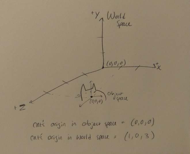
In addition, the rest of the vertices on that cat’s mesh will have different values to describe their position whether we’re looking at them in the cat’s object space or the world space.
Let’s skip over exactly how we create coordinate spaces for now, as that gets a bit complicated, and often frameworks will provide some basic coordinate space matrices for you. (For example, Unity provides built-in shader variables for the View-Space and Projection-Space matrices.)
We use vectors, scalars, and matrices to represent 3D geometry because the math we can do with them (thanks to linear algebra) allows us to represent lots of different transforms necessary for computing the movement of 3D points through space. Let’s look at some examples of what we can do!
Vector Addition & Subtraction
Vector addition is fairly straightforward: mathematically, we add the values of each vector that correspond to the same placement of the other. We can only add vectors of the same degree (same number of values), and the result is always a vector of the same degree as the input vectors.
If our vectors represent positions, we can interpret vector addition as applying the displacement of both positions from the origin, giving us a new position.
For example, vector subtraction can give us the displacement between two points. If we wanted to create a vector describing a ray of light coming from a light source at point L and hitting the vertex A, we would subtract A-L.

Vector Magnitude
The magnitude of a vector is computed as the square root of the sum of the square of each component. If our vector is a point in 3D space, then its magnitude is the length of the vector!
We usually denote the magnitude of a vector N as |N|.
We could, for example, after using vector subtraction to get the vector describing the displacement between L and A, as above, then we could compute the length of A – L to get the distance between L and A.
Vector Cross Products & Surface Normals
Cross products are a way of multiplying two 3D vectors which gives us a new 3D vector which is perpendicular to both original vectors. Here, we see the cross product of AxB resulting in the vector C:

If A and B are parallel, then the cross product results in 0.
A surface normal describes the direction the surface of a polygon is pointing in. Surface normals are incredibly important for lighting calculations, as we can use more vector math to describe the intensity of lighting on a surface by comparing the angle between the surface and the lighting.
You probably won’t need to calculate your own surface normals, but if you do, you can use cross products! Assuming that all of the points on the polygon lie on the same plane, ie, it is co-planar, the direction a surface is pointing in is perpendicular to its edges. Thus, we can use the cross product of any two edges on that polygon to obtain the surface normal. As we just learned, we can determine the vector describing these edges by subtracting the positions of each vertex.


Vector Normalization
Next, let’s address the questions of what is ‘normalization’ and how it relates to surface normals.
Normalizing a vector means transforming it so that its magnitude is 1 while still retaining the same information other than magnitude. For a 3D vector, this would mean transforming the length of the vector to 1 while retaining the information about the vector’s direction from the origin.
Note how, in the drawing below, the normalized vector n is still pointing along the same direction as N, but has a length of 1:

Vector normalization can be calculated as the vector divided by its magnitude:
given N = (x, y, z)
n = (x/|N|, y/|N|, z/|N|)
Normalization is important for many calculations in which the magnitude of the vector is unimportant, and therefore contributing unnecessary information to a calculation. We usually calculate and store surface normals as normalized vectors for this very purpose. Let’s see an example of how normalized vectors are useful!
Vector Dot Products
We mentioned earlier that we can use a vector representing a surface normal and a vector representing a ray of light to do lighting calculations. Dot products help us do just that!
Dot products can be calculated two ways: an algebraic way using the values inside the vectors, or as the cosine of the angle between two vectors multiplied by the magnitude of each vector.
given t = angle between a and b
a * b = |a||b|cos(t)
If the vectors are normalized (as we just learned, have a magnitude of 1), this means that the dot product of the two vectors is simply the cosine of the angle between them.
given |a| = |b| = 1
a * b = |a||b|cos(t)
= 1*1*cos(t)
= cos(t)

The dot product between two normalized vectors is always a scalar with a value from -1 to 1. Therefore, we can use the dot product to get information about the angle between two normalized vectors, even without the value of the angle itself.
The higher the dot product is, the closer the angle between the two vectors. If the product is -1, the vectors are facing directly opposite; if it’s 1, they’re facing in the exact same direction; if it’s 0, they’re at a right angle.
In the drawing below, the vector A is shown with many different possible vectors B with which to take a dot product to help illustrate this concept:

Having information about the angle between two vectors is key to many lighting schemes. Let’s assume we have a light vector that points from a light source to a vertex on an object. If we take the dot product between the surface normal and the light vector, we gain information about that surface’s angle with the light. A surface pointing away from the light will receive less light than one pointing towards the light.

Dot products have a ton of usage outside of lighting calculations. You could, for example, determine whether an enemy was behind or in front of the player by checking to see if the dot product between the player and enemy position was positive or negative.
Matrix * Vector Multiplication
As mentioned earlier, all points in 3D space are represented relative to an origin. We describe these origins with 4×4 matrices. I won’t get in to how we create these bases, as it gets a little complicated, and you probably won’t be calculating your own bases when you’re just starting out.
As you may have guessed from the section title, we can multiply a vector by a transformation matrix to convert from one basis to another.
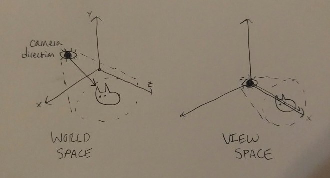
One of the most important uses for transforming from one basis to another occurs in almost every vertex shader: transforming a vertex position from object to view space. ‘View space’ usually describes a basis relative to the camera, with the camera at the origin and pointing along the z-axis. The position input to a vertex shader is almost always stored in object space, relative to the center (or some other defined origin) of the object. However, for all kinds of lighting calculations, and for all later steps of the rendering process to computer correctly, we need that vertex position in world space. If you’ve ever written a shader in Unity, you’ve noticed there’s a built-in matrix to describe the transformation to world space called UNITY_MATRIX_MV which makes this calculation super quick and easy.
Fin
Phew, we sure did get through a LOT today!! I hope you learned something new or maybe had a concept clarified that’s been foggy to you.
For your continued education, I strongly recommend you pick up 3D Math Primer for Graphics and Game Development. They do a much more thorough job explaining the concepts presented in this tutorial. If you’re really interested in continuing to learn about shader writing, you should also consider checking out some of the other resources listed in my side bar, and maybe the rest of my tutorials!
If y’all have any questions about writing shaders in Unity, I’m happy to share as much as I know. I’m not an expert, but I’m always willing to help other indie devs 🙂 And do give me feedback about the tutorials, I love hearing from y’all!
Good luck,
Linden Reid @so_good_lin

Nice Work ! I was really helpful , keep posting stuff like that , Thanks
LikeLike