

Hey y’all! We’re going to learn about several different shader techniques in this tutorial. The distortion effect in particular was covered in the ice tutorial, but we’re going to re-learn it here in a new light.
Basically, this heat distortion shader was achieved by creating a flat plane mesh and applying a material with a shader that does the following:
- Billboard the plane to the camera view & draw it on top of everything
- Grab the camera’s rendered texture
- Distort the texture sample position
- Use the distorted position to sample & draw the camera texture
For your reference, here’s the final code for the distortion fire shader.
Let’s jump right in!
Billboarding
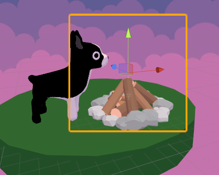
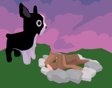
The goal of billboarding a plane is to force it to always look at the camera (or some other position). For example, the output of this section of the tutorial will look like this. Notice how the plane is always facing the view position.
Let’s start by setting up a vertex and fragment shader that just output a flat white color.
vertexOutput vert(vertexInput input)
{
  vertexOutput output;
  output.pos = input.vertex;
  return output;
}

float4frag(vertexOutput input) : COLOR
{
  return float4(1,1,1,1);
}
Now, in the vertex shader, we’re going to write the code to billboard the vertices.
First of all, it’s important to know a couple of Unity’s built-in matrices.
UNITY_MATRIX_MV is the model*view matrix. Multiplying a vector in model space by this matrix transforms the vector to view space.
UNITY_MATRIX_P is the projection matrix, which describes the basis for projection space, which describes the actual screen being rendered to.
In most vertex shaders, we want to convert the model-space input vertex to a projection-space position. Normally, when we want to convert a vertex from model (object) space to a position on screen, we call UnityObjectToClipPosition(input.vertex), which multiplies the vertex position by the MVP (model-view-projection) matrix. This transformation takes the vector from model space, to view space, to projection space.
To do the billboard effect, we first want to convert the object’s origin to view space by multiplying by the model*view matrix. Then, we place the vertex as an offset from that origin, which is in view space. Adding the vertex position after converting to view space keeps the vertex positions camera-aligned.
After that, we can then multiply by the projection matrix to put this position into projection space.
Here’s what it looks like in code:
float4 pos = input.vertex;
// transform origin to view space
float4 originInViewSpace = mul(UNITY_MATRIX_MV, float4(0, 0, 0, 1);
// translate view space point by vertex position
float4 vertInViewSpace = originInViewSpace + float4(pos.x, pos.z, 0, 0);
// convert from view space to projection space
pos = mul(UNITY_MATRIX_P, vertInViewSpace);
output.pos = pos;
Your plane should now be facing the camera position like the gif above!
Drawing On Top of Everything
A very small, but very important effect for this shader is to make it draw on top of everything behind it.
If you noticed in the billboarding gif, the plane is partially behind the campfire, as I placed it in the center. This is important so that the billboarded texture always remains at the center of the campfire, but it means the plane, and therefore the effect, won’t see the pixels in front of it.
To remedy this, we just need to tell the ZTest, or depth test, to always draw this object in front of everything else. Add this line of code right inside your Pass block:
ZTest Always
And your texture should draw on top of everything!
Distortion
The basic premise of the distortion effect is that our shader grabs the camera texture behind the plane and randomly moves the UV position that it uses to sample that texture.
Unity makes getting the camera texture easy with the GrabPass feature. Inside your SubShader tag, add the GrabPass syntax to grab the screen behind the object and put the data in _BackgroundTexture:
GrabPass {
  "_BackgroundTexture"
}
Make sure to add _BackgroundTexture inside the CG code also:
sampler2D _BackgroundTexture;
Now, let’s extend our vertex shader to output the screen texture grab position and extend our fragment shader to sample the background texture (instead of outputting a plain white value).
We can use Unity’s ComputeScreenGrabPos function to easily get the correct screen texture coordinates. (Remember this object is now projected in screen space!)
vertexOutput vert(vertexInput input) {
  vertexOutput output;

  // billboard
  float4 pos = input.vertex;
  pos = mul(UNITY_MATRIX_P, mul(UNITY_MATRIX_MV, float4(0,0,0,1)+float4(pos.x, pos.z, 0, 0));
  output.pos = pos;

  // grab coordinates
  output.grabPos = ComputeScreenGrabPos(output.pos);

  return output;
}

float4 frag(vertexOutput input) : COLOR {
  return tex2Dproj(_BackgroundTexture, input.grabPos);
}
Your texture should now basically be invisible, as it’s just drawing the background behind it. Here’s the game view with the plane highlighted, showing that it’s definitely there and rendering whatever’s behind it:
Now that we have the grab pass working, let’s distort the sample position, which I called grabPos.
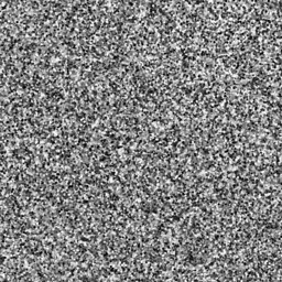
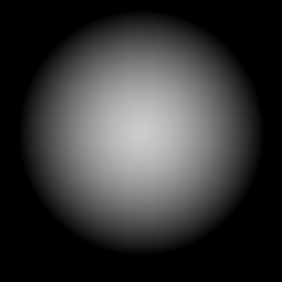
We’ll want to change the grab position for each vertex randomly, which you could either write a random function for, or sample a noise texture. I went with the latter; here’s what my noise texture looks like.
First of all, let’s add a float called Strength to our Properties block to determine how far we’re pushing the screen pixels around, and a Noise texture.
_Strength("Distort Strength", float) = 1.0
_Noise("Noise Texture", 2D) = "white" {}
Now, read the noise texture value at our regular texture coordinates (not our screen grab coordinates!) and add that to our grab position:
// grab coordinates
output.grabPos = ComputeScreenGrabPos(output.pos);
float noise = tex2Dlod(_Noise, float4(input.texCoord, 0)).rgb;
output.grabPos.x += noise * _Strength;
output.grabPos.y += noise * _Strength;
With the strength tuned (mine is at 10 for this), you should now get a static, kinda ugly distortion:
To make this distortion look a little prettier and do a nice wave animation, let’s modify the noise value with _Time and with a trig function.
I also added another float Property called _Speed to control the speed of the wiggle animation.
// grab coordinates
output.grabPos = ComputeScreenGrabPos(output.pos);
float noise = tex2Dlod(_Noise, float4(input.texCoord, 0)).rgb;
output.grabPos.x += cos(noise*_Time.x*_Speed) * _Strength;
output.grabPos.y += sin(noise*_Time.x*_Speed) * _Strength;
We’re almost there! You should now have a nicely wiggling distort effect:

… However, you prooobably noticed the ugly edges created by this effect. Because we’re drawing on a square plane, the wiggle harshly stops and starts at the edges of the plane.
To counter this, let’s add a strength filter so that the distortion is strongest in the middle and tapers off towards the edges. You could calculate this simply by using the UV coordinate’s distance from the center of the texture, but I decided to use another texture for the strength filter.
My texture looks like this, although it might be fun to experiment with other shapes! Brighter areas indicate stronger distortion, and dark areas indicate lower distortion.
Don’t forget to add this filter to your Properties block, and set this texture:
_StrengthFilter("Strength Filter", 2D) = "white" {}
And then, in your distortion effect, sample the texture as normal, and multiply that value by our strength:
// grab coordinates
output.grabPos = ComputeScreenGrabPos(output.pos);

float noise = tex2Dlod(_Noise, float4(input.texCoord,0)).rgb;
float filter = tex2Dlod(_StrengthFilter, float4(input.texCoord,0)).rgb;

output.grabPos.x += cos(noise*_Time.x*_Speed) * filter * _Strength;
output.grabPos.y += sin(noise*_Time.x*_Speed) * filter * _Strength;
And there you have it! After some tuning, your shader should now taper off towards the edges, removing the edge problem.

Fin
Awesome, you made it! We learned a ton today, from billboarding, to screen grab textures, to clever ways to use noise and animation, to ignoring the depth test.
Here’s the final code for the distortion fire shader again, under a non-commercial open-source license.
If y’all have any questions about writing shaders in Unity, I’m happy to share as much as I know. I’m not an expert, but I’m always willing to help other indie devs 🙂 And do give me feedback about the tutorials, I love hearing from y’all!
Good luck,
Lindsey Reid @so_good_lin

Hi, thank you for your tutorial.
Can this shader distort 2D Sprite or particle systems?
It seems that sprites will disappear when covered by a plan with this shader?
LikeLike
Hi, thank you for your tutorial, it’s clear and super understandable, especially for shader beginners.
Although I have one question, in the billboard shader, when you translate view space point by vertex position, why did you use pos.x and pos.z, instead of pos.x and pos.y?
LikeLike
thank you so much
LikeLike
Nice shader 🙂
I had a little issue using it because of the vertex calculation in vert function, which was giving only a tiny little thumbnail of the grabbed zone. To had it working i simply edited like this.
vertexOutput output;
// use UnityObjectToClipPos from UnityCG.cginc to calculate
// the clip-space of the vertex
output.pos = UnityObjectToClipPos(input.vertex);
// use ComputeGrabScreenPos function from UnityCG.cginc
// to get the correct texture coordinate
output.grabPos = ComputeGrabScreenPos(output.pos);
LikeLike
Hi Linden, thanks so much for this great tutorial. I’m trying to replicate your work, and things are working just like you said they would, but I’m a bit confused as to why they are. Currently, my shader looks like this:
“`
Shader “Custom/Distort”
{
SubShader
{
Pass
{
//ZTest Always
CGPROGRAM
#pragma vertex vert
#pragma fragment frag
#include “UnityCG.cginc”
struct vertexInput
{
float4 vertex : POSITION;
float3 texCoord : TEXCOORD0;
};
struct vertexOutput
{
float4 pos : SV_POSITION;
};
vertexOutput vert(vertexInput input)
{
vertexOutput output;
float4 pos = input.vertex;
// transform origin to view space
float4 originInViewSpace = mul(UNITY_MATRIX_MV, float4(0, 0, 0, 1));
// translate view space point by vertex position
float4 vertInViewSpace = originInViewSpace + float4(pos.x, pos.z, 0, 0);
// convert from view space to projection space
pos = mul(UNITY_MATRIX_P, vertInViewSpace);
output.pos = pos;
return output;
}
float4 frag(vertexOutput input) : COLOR
{
return float4(1,1,1,1); // billboard test
}
ENDCG
}
}
}
“`
And it’s indeed giving me a plane whose normal is always facing the camera. FTR, its attached to a material which is attached to an out-of-the-box Unity Plane GameObject. What confuses me, though, is that I see a 1×1 plane no matter how I scale the Plane. So even if I set the Scale vector in the Transform section of the inspector to X=1, Y=0, Z=10, I still get a 1×1 plane staring at me no matter where I rotate. I now be getting greater values from `pos.z`, that should translate into a taller looking white plane after I run through my shader? I must be missing something trivial here, but I’ve spent hours searching and haven’t been able to figure out what. Any help would be greatly appreciated!
LikeLiked by 1 person
I’m getting this error:
Shader properties can’t be added to this global property sheet. Trying to add _BackgroundTexture_TexelSize
LikeLike
Thank you so much
LikeLike
Hello,
If you’re rendering a scene to an FBO, how do you implement this? You can’t read from a texture that is bound to an FBO. This is regarding your screen grab with _BackgroundTexture. In other words, your _BackgroundTexture is bound to an FBO. How do you make this work?
I’m not using Unity.
Thanks for any input.
LikeLike
Hello, first of all thank you for the quick and clear explanation!
I only have one doubt, if I always render the distortion plane in front of everything, what if there is an object between me and the fireplace? I should not be able to see the distortion since there is an object in between. Did I misunderstand?
LikeLike