

If you follow me on Twitter, you’ll know that I posted a poll to determine the content of this tutorial! With almost half the votes, an introduction to procedural geometry was the winner.
Also, sorry for lack of shader tutorial this week… was at PAX lol :p I’ve got a few ideas for this weekend’s tutorial; what do y’all want to see?
— Lindsey Reid (@thelindseyreid) January 16, 2018
So, this tutorial will teach you the bare basics of creating procedural geometry in Unity!
Unity has a tutorial on creating a plane in code, but it’s lacking in pictures and assumes that you already know what “vertices” and “triangles” mean. A few other people have written good tutorials on procedural geometry, but I wanted to write one that easily flows into the other procedural geometry tutorials that I write.
Although this tutorial uses Unity, all of the concepts (other than the specific calls to Unity’s API) are applicable to most other engines.
This tutorial assumes you know:
- Basics of using Unity (creating objects, attaching scripts, using the inspector)
- How to code in C# (or at least a similar language)
This tutorial will teach you:
- The high-level of how 3D geometry is represented in code (vertices and triangles)
- How to use these concepts to create geometry with code
- How to use Unity’s Mesh API to create geometry
- How to create a plane mesh in code
- How to create a 3D cube (part 2)
- How normals & UVs work (part 3)
- How to texture procedural meshes (part 4)
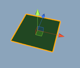
Here’s what we’re going to learn to create today! It’s not fancy, but it’s important to understand all of the basics before moving on.
How Meshes Are Stored
Before we can create geometry, we need to understand how they’re stored in code.
Basically, all meshes are stored as lists of vertices and triangles. (Sometimes the triangles can be stored as quads or polygons of higher degree, but let’s focus on triangles for now.)
Vertices define the 3D points in space that make up a mesh. In the picture below, I drew a handful of red dots where vertices exist on the teapot mesh. I’m too lazy to draw them everywhere, so imagine these dots also exist everywhere that you see lines intersecting. In Unity, one vertex is stored as a 3D vector, or Vector3, where the 3 values represent the 3D coordinates of the vertex.
Triangles define the edges that connect the 3 vertices in order to define the surface of a triangle. The lines on the mesh below show where all of the triangles are that connect the vertices.

Normals and UVs are also important for defining a mesh, especially with regards to texturing and lighting the mesh. However, for part 1, we’re just going to focus on creating vertices and triangles. Unity will do the grunt work with normals for us for now!
How to Create a Basic Plane
Now, on to the code! Firstly, create a new script with a public MeshFilter property and attach it to an object with a MeshFilter and MeshRenderer component in your hierarchy. Then, drag that object into the public property to assign it.
Here’s the skeleton of the script; we’re going to be working in the Start() function from now on.
using UnityEngine;

public class ProcGeo : MonoBehaviour {

    public MeshFilter meshFilter;
    public float width = 1.0f;
    public float length = 1.0f;

    void Start () {
        // mesh stuffs gonna go here
    }
}
First, let’s define a new Mesh and assign it to our MeshFilter. After this step, you should have no compile errors, and after you press play, your existing mesh should disappear.
Mesh mesh = new Mesh();
meshFilter.mesh = mesh;
Now, let’s define the vertices of the mesh. Since we’re creating a rectangular plane, we only need 4 vertices, one for each corner.
Drawing a picture ALWAYS helps create geometry, so here’s a poorly-lit one to help you visualize the plane.
Width defines the size of the plane along the X-axis, and Length defines its size along the Z-axis. This picture defines the (x,z) coordinates for the vertices, since the y-coordinate for all of them is 0.
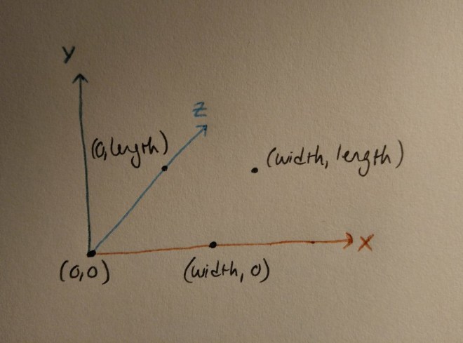
And here’s what it looks like in code. Unity uses Vector3 to represent the 3D coordinates of the vertices, so we’ll create an array of them and then assign that back to our mesh.
Vector3[] vertices = new Vector3[4];

vertices[0] = new Vector3(0,        0,  0);
vertices[1] = new Vector3(width,    0,  0);
vertices[2] = new Vector3(0,        0,  length);
vertices[3] = new Vector3(width,    0,  length);

mesh.vertices = vertices;
Triangles are defined by storing groups of 3 vertex indices.
For example, if I store a triangle as (0, 1, 2), then I’ve created a triangle out of the vertices at index 0, 1, and 2 in the vertex list.
In this list, that means I’ve created a triangle that goes from position (0, 0, 0) to (width, 0, 0) to (0, 0, length).
Winding order is also an important concept when creating triangles. The winding order of the triangle, or the direction (clockwise or counter-clockwise) that the index list moves in when visualized in 3D space, determines the direction that the front of the triangle surface will point. Since many shaders don’t draw the back face of the triangle, the front face, and therefore the winding order, determines what side of the triangle will be drawn. Unity uses clockwise winding order to determine the front face of a triangle.
Let’s visualize the triangles.

The numbers on each vertex represent their index in the vertex list that we made earlier.
The triangle on the left can be stored as (0, 2, 1). See how when we move from vertex 0, to 2, to 1, we move in a clockwise direction? Try drawing your own picture if you’re having trouble visualizing this. We can store the triangle on the right as (2, 3, 1).
Now, we’re ready to store the triangles! Since we have 2 triangles, and each triangle stores 3 indices, our triangle list needs to be 6 long. Wow, math! Unity (and many other engines) store triangles as a simple array of integers, with every 3 entries indicating a triangle.
int[] tris = new int[6];

tris[0] = 0;
tris[1] = 2;
tris[2] = 1;

tris[3] = 2;
tris[4] = 3;
tris[5] = 1;

mesh.triangles = tris;
mesh.RecalculateNormals();
Fin
Hopefully, you now understand the basics of how meshes are stored in code- specifically, how vertices and triangles work. In the next part of this tutorial, coming later this week, we’ll go over normals, UVs, and some more complicated shapes. In the meantime, try playing with the properties in this tutorial- or, if you’re feeling brave, go straight for more complicated algorithms.
As always, here’s the full code for this tutorial under an open-source license.
If y’all have any questions about writing procedural geometry or shaders in Unity, I’m happy to share as much as I know. I’m not an expert, but I’m always willing to help other indie devs 🙂 And do give me feedback about the tutorials, I love hearing from y’all!
Good luck,
Lindsey Reid @so_good_lin

Hi. I’m a beginner who’s read a few of your tutorials and I think they’re great.
I actually battled the issue of creating a simple plane mesh recently and couldn’t quite get the code on Unity’s page, this is a much easier read. Thank you so much and I’m looking forward to the continuation of this series. 🙂
LikeLiked by 1 person
I am SO glad to hear that! What helped you the most? Different wording, or pictures? (For me, pictures always make a huge difference, lol.)
LikeLike