

(important disclaimer: this work represents me only & not the company I work for.)
I was inspired by an episode of the Powerpuff Girls for this effect. I wanted to create this effect of color spreading in a black and white world, but to do the effect in world space coordinates so that you can see the color crawling over objects instead of flatly spreading across the screen like in the show.
I created this effect in Unity’s new Lightweight Rendering Pipeline, a built-in example of a Scriptable Rendering Pipeline. All of the concepts still apply to other pipelines, but some of the built-in functions or matrices might have different names. I also used the new post-processing stack, but I omitted explaining how the basics of how to set it up, as I think other guides already cover this pretty well, such as this video.
For tutorial updates, follow me on Twitter. I also do Q&A coding streams on Twitch, and you can always DM me on Twitter or ask me questions in the Twitch chat about shader stuff 😀
Grayscale Post-Processing Effect
Just for reference, here’s what our scene looks like with no post-processing effects.

I used Unity 2018’s new Post-Processing package for this effect, which you can download in your package manager. If you’re unfamiliar with how to use it, I recommend this tutorial.
I wrote a custom effect by extending the PostProcessingEffectSettings and PostProcessEffectRenderer classes in C#, which you can see the source code for here. I didn’t actually do anything interesting with these effects from the CPU side (in the C# code) other than expose a bunch of properties to the Inspector, so I’m going to skip explaining how to do that in this tutorial. Hopefully, the code is pretty self-explanatory 🙂
Let’s jump into the shader code and start with the grayscale effect first. We’re not going to change the shaderlab file, input structs, or vertex shader throughout this tutorial, so you can look at them in the source code here. Instead, let’s look at the fragment shader specifically.
To convert a color to grayscale, we reduce each pixel to a luminance value, which describes its brightness. We do this by taking the dot product of the camera texture’s color value and a weighted vector which describes how each color channel contributes to the overall brightness of the color.
Why use a dot product? Remember that dot products can be evaluated as:
dot(a, b) = ax * bx + ay * by + az * bz
In this case, we’re multiplying each channel of the color value by a weight. Then, we add those products together to reduce them to a single scalar. When an RGB color has the same value in the R, G, and B channels, the color turns out gray.
Here’s what the shader code looks like:
float4 fullColor = SAMPLE_TEXTURE2D(_MainTex, sampler_MainTex, i.screenPos);
float3 weight = float3(0.299, 0.587, 0.114);
float luminance = dot(fullColor.rgb, weight);
float3 greyscale = luminance.xxx;

return float4(greyscale, 1.0);
With your basic shader set up correctly, the post-processing effect should make the whole screen grayscale.

Drawing the Color Effect in World Space
Because this is a post-processing effect, we don’t have any information about the geometry in the scene in the vertex shader. At the post-processing stage, the only information we have is the image the camera has rendered and clip-space coordinates for sampling it. However, we want to make the color effect spread over objects as if it’s happening in the world and not just on the flat screen.
To draw this effect on the geometry in the scene, we’ll need the world-space coordinates of each pixel. To get from clip-space to world-space coordinates, we’ll need to do a coordinate space transformation.
Normally, to move from one coordinate space to another, all you need is a matrix that defines the transformation from coordinate space A to B. To get from A to B, you multiply the vector in coordinate space A by this transformation matrix. In this case, we’re going to move from clip space -> view space -> world space, so we need a clip-to-view-space matrix and a view-to-world-space matrix, which are provided by Unity.
However, our clip-space coordinates provided by Unity are missing the z value, which defines the pixel’s depth, or distance from the camera. We need this value to get from clip space to view space. Let’s start with that!
Getting the Depth Buffer Value
If enabled, the rendering pipeline draws a texture that stores the z values in view space, called the depth buffer. We can sample this buffer to get that missing z value for our clip space coordinate!
Firstly, make sure your depth buffer is actually rendering by clicking “Add Additional Data” on your camera in the Inspector and checking the “Requires Depth Texture” check box. Also, make sure “Allow MSAA” is checked on your camera. I don’t know why that box has to be checked for it to work, but there you go :p If your depth buffer is drawing, you should see a “Depth Prepass” step in your frame debugger.
Make sure to create a sampler for the _CameraDepthTexture in your hlsl file.
TEXTURE2D_SAMPLER2D(_CameraDepthTexture, sampler_CameraDepthTexture);
Now, let’s write a GetWorldFromViewPosition function, and just use it to test the depth buffer for now. (Later, we’re going to extend it to actually get the world position.)
float3 GetWorldFromViewPosition (VertexOutput i) {
  float z = SAMPLE_DEPTH_TEXTURE(_CameraDepthTexture, sampler_CameraDepthTexture, i.screenPos).r;
  return z.xxx;
}
In the fragment shader, draw the depth texture sample value.
float3 depth = GetWorldFromViewPosition(i);
return float4(depth, 1.0);
Here’s what my results look like with just a hilly plane in the scene (I turned off all of the trees to make testing the world space values easier later). Yours should look similar, with black and white values describing the geometry’s distance from the camera.

Here are a few troubleshooting things to try if yours isn’t working:
- Make sure your camera is set to render a depth texture.
- Make sure MSAA is enabled on your camera.
- Fiddle with your camera’s near and far planes.
- Make sure whatever objects you’re expecting to see in the depth buffer use a shader that has a depth pass, which ensures the object draws to the depth buffer. Any default shader in the LWRP should do so.
Getting the World Space Value
Now that we have all of the information we need for our clip-space coordinates, let’s convert to view-space and then world-space coordinates.
Note that the transformation matrices we need for these operations aren’t already provided in the SRP library. They are, however, provided in Unity’s C# library, so I set them in the shader in the Render function of the ColorSpreadRenderer:
sheet.properties.SetMatrix("unity_ViewToWorldMatrix", context.camera.cameraToWorldMatrix);
sheet.properties.SetMatrix("unity_InverseProjectionMatrix", projectionMatrix.inverse);
Now, let’s expand our GetWorldFromViewPosition function.
Firstly, we need to get to the view-space position by multiplying the clip-space position by the InverseProjectionMatrix. We also need to do some other voodoo magic to the screen position that has to do with how Unity stores the clip-space position.
Finally, we can multiply our view space position by the ViewToWorldMatrix to get the world-space position.
float3 GetWorldFromViewPosition (VertexOutput i) {
  // get depth value
  float z = SAMPLE_DEPTH_TEXTURE(_CameraDepthTexture, sampler_CameraDepthTexture, i.screenPos).r;

  // get view-space position
  float4 result = mul(unity_InverseProjectionMatrix, float4(2*i.screenPos-1.0, z, 1.0));
  float3 viewPos = result.xyz / result.w;

  // get world-space position
  float3 worldPos = mul(unity_ViewToWorldMatrix, float4(viewPos, 1.0));
  return worldPos;
}
Let’s set up a test to make sure our world-space positions are correct. To do this, I wrote a shader that only outputs an object’s world-space position, which is an easy enough calculation from a regular shader that I could trust it to be correct. Turn your post-processing effect off and screenshot the results of this world space test shader. Mine looked like this, when applied to just the ground plane in the scene:

(Note that world space values go much larger than 1.0, so don’t worry about these colors making much sense; rather, check to see if the results look the same between the “correct” and “calculated” answers.) Next, make sure to put the regular (not world-space-test) material back on your test object, and then turn the post-processing effect back on. My results looked like this:

This looks just like the test shader I wrote, so the world space calculations are probably correct!
Drawing a Circle in World Space
Now that we have the world-space positions, we can draw a circle of color in the scene! We want to define a radius within which the effect will draw color, and outside of, the effect will draw grayscale. We need tuning values for the radius of the effect (_MaxSize) and the center of the circle (_Center) to define it. I defined these values in the ColorSpread C# class to expose them to the inspector. Let’s expand our fragment shader to check if the current pixel is inside the radius of our circle:
float4 Frag(VertexOutput i) : SV_Target
{
  float3 worldPos = GetWorldFromViewPosition(i);

  // check if distance is inside bounds of max radius
  // choose greyscale if outside, full color if inside
  float dist = distance(_Center, worldPos);
  float blend = dist <= _MaxSize? 0 : 1;

  // regular color
  float4 fullColor = SAMPLE_TEXTURE2D(_MainTex, sampler_MainTex, i.screenPos);

  // grayscale
  float luminance = dot(fullColor.rgb, float3(0.2126729, 0.7151522, 0.0721750));
  float3 greyscale = luminance.xxx;

  // decide whether to use color or grayscale
  float3 color = (1-blend)*fullColor + blend*greyscale;

  return float4(color, 1.0);
}
Finally, we should be able to draw color based on whether or not it’s inside a radius in world space. Here’s what the basic effect looks like!
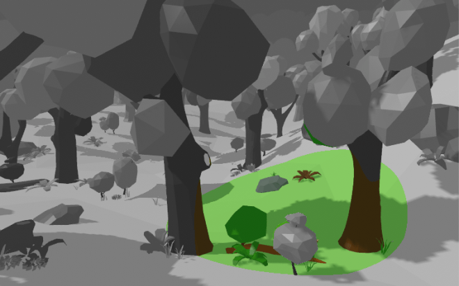
Adding Special Effects
I’m going to focus on just a couple more techniques used to get this to look like paint spreading on the ground. The full effect has even more going on, but this tutorial is already pretty huge, so let’s focus on the most important ones.
Animating the Circle Growth
We want this effect to spread over the world, like it’s growing. To do that, let’s change the size of the radius over time.
_StartTime marks when you want the circle to start growing. In my project, I used an extra script to allow you to click anywhere to start growing the circle; in that case, the start time is set as whenever you clicked on screen.
_GrowthSpeed defines how fast the circle will grow.
// calculate radius based on animation starting time & current time
float timeElapsed = _Time.y - _StartTime;
float effectRadius = min(timeElapsed * _GrowthSpeed, _MaxSize);

// clamp radius so we don't get weird artifacts
effectRadius = clamp(effectRadius, 0, _MaxSize);
You’ll also need to update our distance check to compare the current distance against the growing effect raidus instead of the _MaxSize.
// check if distance is inside bounds of current effect radius
// choose greyscale if outside, full color if inside
float dist = distance(_Center, worldPos);
float blend = dist <= effectRadius? 0 : 1;

// rest of the color stuff...
Here’s what the result should look like:
Adding Noise to the Radius
I wanted this effect to look more like paint spreading than just a circle growing. To do this, let’s add noise to the radius of the effect so that the spread is uneven.
Firstly, we need to sample the texture in world space. Our i.screenPos uv coordinates are in screen space, and if we sample with those, the effect shape would move with the camera; so, let’s use our world space coordinates instead. I added a _NoiseTexScale parameter to control the scale of the noise texture sample, as the world space coordinates are quite large.
// get world-space sample position for noise texture
float2 worldUV = worldPos.xz;
worldUV *= _NoiseTexScale;
Now, let’s sample the noise texture and add that value to the effect radius. I used the _NoiseSize scale for more control over the size of the noise.
// add noise to radius
float noise = SAMPLE_TEXTURE2D(_NoiseTex, sampler_NoiseTex, worldUV).r;
effectRadius -= noise * _NoiseSize;
After some tuning, here’s what our result looks like:

Fin
Don’t forget to follow me on Twitter for tutorial updates and Twitch for coding streams! 😀 (I also stream gaming occasionally, so don’t be surprised if you log on and I’m in Kingdom Hearts pajamas playing KH3…)
Credits:
- All of the models in the projects are from this LowPoly Environment Pack from the Unity store.
- Thank you to Unity’s ScreenSpaceReflections effect for helping me figure out how to get the 3d view space position from 2d screen space UVs.
If y’all have any questions about writing shaders in Unity, I’m happy to share as much as I know. I’m not an expert, but I’m always willing to help other indie devs 🙂 And do give me feedback about the tutorials, I love hearing from y’all!
Good luck,
Linden Reid @so_good_lin

Hi Linden! Just discovered your blog and I’ll definitely binge all of them 😀
Thanks for sharing these tutorials!!
LikeLike
Thank you for the kind words 🙂
LikeLike
Great job!
Thank you for your sharing.
LikeLike
Excellent! Thanks!
LikeLike
Hey this looks great, but doesnt work for me in Unity 2020.2.1f1
I trying your github version and no luck
Do you have an update for this which works, I would love to experiement with it. Thanks
LikeLike
Heello nice blog
LikeLike