

DISCLAIMER #1: Code presented here is pseudocode that does NOT necessarily reflect production Limit Theory code.
DISCLAIMER #2: This tutorial assumes you have at least basic knowledge of 3D geometry and related math.
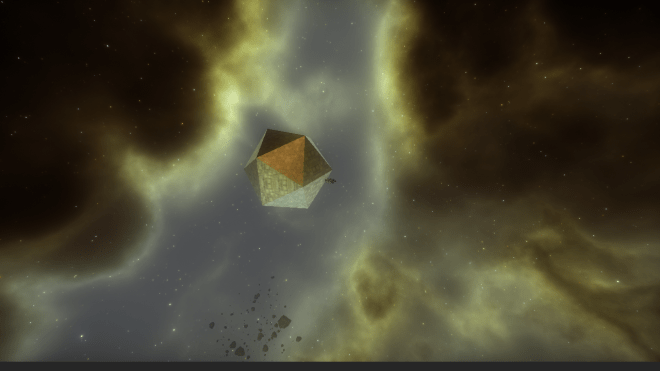
This week, I’m writing as many procedural generation tutorials as I can to help out participants of #PROCJAM! Today, I’m going to explain how to extrude the triangles in a mesh. For the purpose of this tutorial, extrusion is the process of copying all of the verticies in a triangle and translating them in the direction of the surface normal, so that you end up with a triangular prism.

As with the stellation tutorial, let’s focus on just one triangle before we get to the rest of the mesh. Let’s note the triangle’s three vertex positions as three 3D vectors (or Vec3) called v1, v2, and v3 with x, y, and z coordinates.
First, we’ll need to define the axis that we want to extrude the face on. For that, we need to define the surface normal of the triangle.
Vec3 e1 = v2 - v1
Vec3 e2 = v3 - v2
Vec3 normal = e1:cross(e2)
normal = normal:normalize()
With that information determined, we can begin the extrusion. We want to create three new vertices that are translated in the direction of the normal. To translate each vertex, we add the normal to each vertex. “h” in this pseudocode is an optional distance to extrude the vertex by. The bigger it is, the longer our resulting pyramid will be.
Vec3 v4 = v1 + (normal * h)
Vec3 v5 = v2 + (normal * h)
Vec3 v6 = v3 + (normal * h)
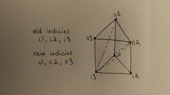
-- top
tri1 = Tri(n1, n3, n2)
-- side
tri2 = Tri(n1, i1, n2)
tri3 = Tri(n2, i1, i2)
-- side
tri4 = Tri(n3, n2, i2)
tri5 = Tri(n3, i2, i3)
-- side
tri6 = Tri(n3, i3, i1)
tri7 = Tri(n3, i1, n1)
-- determine surface normal
Vec3 e1 = v2 - v1
Vec3 e2 = v3 - v2
Vec3 normal = e1:cross(e2)
normal = normal:normalize()

-- create extruded verticies
Vec3 v4 = v1 + (normal * h)
Vec3 v5 = v2 + (normal * h)
Vec3 v6 = v3 + (normal * h)

-- create tris
-- top
tri1 = Tri(n1, n3, n2)
-- side
tri2 = Tri(n1, i1, n2)
tri3 = Tri(n2, i1, i2)
-- side
tri4 = Tri(n3, n2, i2)
tri5 = Tri(n3, i2, i3)
-- side
tri6 = Tri(n3, i3, i1)
tri7 = Tri(n3, i1, n1)
function Extrude (Mesh oldMesh, int h)

newMesh = Mesh()

-- add ALL of the verticies from the old mesh
Vec3[] oldVerticies = oldMesh.verticies
for i = 1, #oldVerticies do
  newMesh:addVertex(oldVerticies[i])
end

-- create new extruded verticies & tris
local vi = #newMesh.verticies
for i = 1, #oldMesh.tris do
  -- old indicies
  int i1 = oldMesh.tris[i].i1
  int i2 = oldMesh.tris[i].i2
  int i3 = oldMesh.tris[i].i3
  -- old verticies
  Vec3 v1 = oldMesh.verticies[i1]
  Vec3 v2 = oldMesh.verticies[i2]
  Vec3 v3 = oldMesh.verticies[i3]

  - normal
  Vec3 e1 = v2 - v1
  Vec3 e2 = v3 - v2
  Vec3 normal = e1:cross(e2)
  normal = normal:normalize()

  -- new vertex
  newMesh:addVertex( v1 + (normal * h) )
  newMesh:addVertex( v2 + (normal * h) )
  newMesh:addVertex( v3 + (normal * h) )

  -- new tris
  -- top
  newMesh:addTri(n1, n3, n2)
  -- side
  newMesh:addTri(n1, i1, n2)
  newMesh:addTri(n2, i1, i2)
  -- side
  newMesh:addTri(n3, n2, i2)
  newMesh:addTri(n3, i2, i3)
  -- side
  newMesh:addTri(n3, i3, i1)
  newMesh:addTri(n3, i1, n1)

  vi = vi + 3
end

return newMesh
end

If you enjoyed this tutorial, see any typos or bugs, or have any other feedback, leave me a comment or tweet at me! You can follow me here on WordPress or on Twitter @so_good_lin. And be sure to keep track of @LimitTheory on Twitter – when it comes out, the production version of all of this code & more will be available for exploring and modding. 🙂
DISCLAIMER: Code presented here is pseudocode that does NOT necessarily reflect production Limit Theory code.

Hi greeat reading your post
LikeLike