

This is an immediate follow-up to Intro to Procedural Geometry, Part 2. If you don’t yet know how to generate a cube, make sure to read Part 1 and 2!
This tutorial assumes you know:
- Basics of using Unity (creating objects, attaching scripts, using the inspector)
- How to code in C# (or at least a similar language)
- The high-level of how 3D geometry is represented in code (vertices and triangles)
- How to use Unity’s Mesh API to create geometry
- How to create a plane mesh in code
- How to create a cube’s vertices and triangles
This tutorial will teach you:
- How normals & UVs work
- How to texture procedural meshes (part 4)
For your reference, here’s the final code for a procedural cube. Make sure to read the linked file and the file titled Shape in the same repository folder!
Let’s get to it!
Shape Class
Since we need to calculate the surface normals per face, we’ll need to create 6 unique faces- creating 24 vertices (4 vertices per face x 6 faces on a cube = 24 total)- in order to correctly calculate the surface normals. Instead of writing a bunch of repeated code, let’s move our code around so that we have a function for filling in the uvs and normals for each face.
First, let’s go ahead and create a new script called Shape for storing all of the vertex, triangle, UV, and normal information. Then, let’s add a CreateQuad() function to it.
public int[] triangles;
publicVector2[] uv;
publicVector3[] normals;
int triOffset = 0;
int vertexOffset = 0;

public Shape (int numVerts, int numTris)
{
  vertices = newVector3[numVerts];
  triangles = newint[numTris];
  uv = newVector2[numVerts];
  normals = newVector3[numVerts];
}

public void CreateQuad ()
{
  // QUAD CODE GOES HERE
}
In addition, let’s refactor our main code to use this class instead of hard-coding a bunch of vertices and triangles.
void CreateBox()
{
   // create a new mesh & assign it to our MeshFilter
  Mesh mesh = new Mesh();
  meshFilter.mesh = mesh;

  // create shape builder
  Shape shape =newShape(8, 36);

  // quads
  // going to focus on just one face for now
  shape.CreateQuad();

  mesh.vertices=shape.vertices;
  mesh.triangles=shape.triangles;
  mesh.uv = shape.uv;
  mesh.normals = shape.normals;
}
Now, let’s write CreateQuad() to be able to assign the vertices and triangles for a single quad. We’re going to focus solely on creating the top face of the cube for now for the sake of simplicity.
public void CreateQuad ()
{
  // vertex indices
  int i1 = vertexOffset;
  int i2 = vertexOffset + 1;
  int i3 = vertexOffset + 2;
  int i4 = vertexOffset + 3;

  // vertices
  vertices[i1] = new Vector3(-1, 1, 1);
  vertices[i2] = new Vector3( 1, 1, 1);
  vertices[i3] = new Vector3( 1, 1, -1);
  vertices[i4] = new Vector3(-1, 1, -1);

  vertexOffset += 4;

  // triangles
  triangles[triOffset] = i1;
  triangles[triOffset+1] = i2;
  triangles[triOffset+2] = i3;

  triangles[triOffset+3] = i1;
  triangles[triOffset+4] = i3;
  triangles[triOffset+5] = i4;

  triOffset += 6;

  // NORMAL CODE GOES HERE

  // UV CODE GOES HERE
}
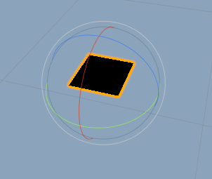
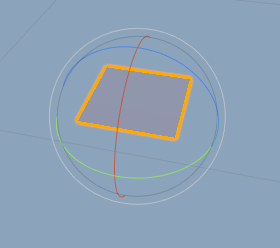
If you run the code up to this point, you should see a single black quad, like this. This shows that we’ve properly defined our vertices and triangles, but haven’t defined UV or normal information yet, so the plane appears totally unlit and un-textured.
Normals and UVs: Overview
Now that we have a firm grasp on how to generate the meshes for 3D procedural geometry, we’re ready to figure out normals and UVs. First, let’s define what they mean.
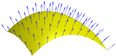
Surface normals define the direction that a triangle is pointing in. Normals are important for calculating lighting and lots of other effects in shaders. Here, for example, is a curved surface, with all of the arrows representing the direction each plane of the surface is pointing in.
UVs give a map of how the object will be textured. They correspond to locations on a flat plane texture, with (0,0) being the bottom-left corner of the plane, and (1,1) being the top-right corner of the plane.
Usually, when an artist creates a 3D model, they also create the UV map for the model, using a combination of a UV-generation tool and hand-editing to create a map that they can use to hand-create textures for the model.
However, since we’re creating the geometry procedurally, we also need to procedurally create the UVs. In this part of the tutorial, we’ll learn how to do that!
In the next part of the tutorial, we’re going to look at an algorithm that you can use to texture almost any kind of mesh called triplanar texturing that doesn’t require you to figure out the UVs in this way. But for now, let’s focus on understanding the basics!
Normal Calculation
Now, let’s look at how to calculate the normals for each face.
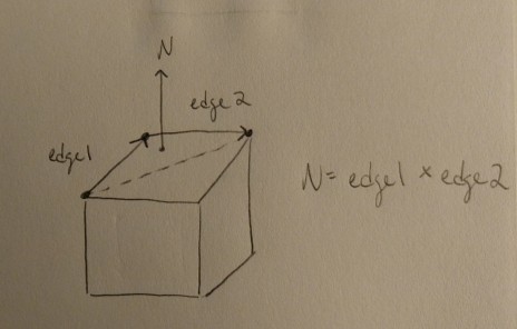
For any triangle, a surface normal can be calculated as the normalized cross product of two edges in the triangle. Recall from the linear algebra class that you didn’t pay attention in that a cross product gives us a vector that’s perpendicular to both of the input vectors. So, a cross product of two edges in the triangles gives us a vector pointing away from those edges, which describes the direction the surface is pointing in.
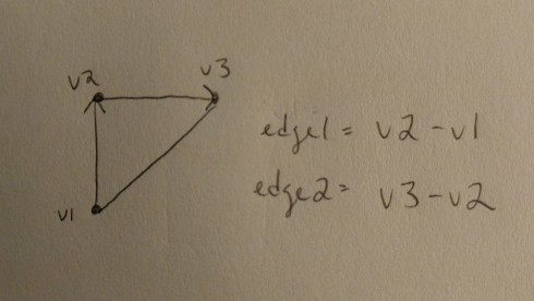
To find two edges in the triangle to use for this calculation, we’ll want to create two vectors pointing from one vertex to another. Specifically, we’ll want them to point in the winding order of the triangle, as this will determine the direction that our cross product points in. As with calculating any basic directional vector, we can calculate these by simply subtracting the position of our destination vertex from the beginning vertex.
A normalized vector is a vector with magnitude 1, which means it only contains the pure directional information, not muddled by the vector length. Surface normals are just that- only a direction- so we need to normalize our cross product.
The code to calculate any surface normal then looks like this:
Vector3 GetSurfaceNormal (Vector3 v1, Vector3 v2, Vector3 v3) {
  // get edge directions
  Vector3 edge1 = v2 - v1;
  Vector3 edge2 = v3 - v2;
  // get normalized cross product
  Vector3 normal = Vector3.Cross(edge1, edge2).normalized;
  return normal;
}
We can then use this for every vertex created in this cube. Let’s expand our CreateQuad function to use the GetSurfaceNormal function.
// normals
Vector3 normal = GetSurfaceNormal(vertices[i1], vertices[i2], vertices[i3]);
normals[i1] = normal;
normals[i2] = normal;
normals[i3] = normal;
normals[i4] = normal;
Note that this algorithm assumes that every triangle in the face is co-planar- that is, they all lie flat on the same plane, and thus have the same surface normal. For our cube, that means that every square face has the same normal. For more complicated geometry, you’ll need to calculate the surface normal per triangle.
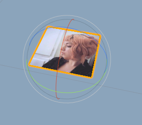
If you run the code up until this point, the quad should now be correctly lit, but incorrectly textured, looking something like this:
UV Calculation
Recall that UV coordinates correspond to locations on a flat plane texture, with (0,0) being the bottom-left corner of the plane, and (1,1) being the top-right corner of the plane.
With that in mind, calculating the UVs for a quad is quite simple. We mainly want to make sure that we keep in mind the position of the vertices we assumed when we created the vertex list.
Let’s add the UV code to CreateQuad():
// UVs
uv[i1] = new Vector2(0, 1); // 0
uv[i2] = new Vector2(1, 1); // 1
uv[i3] = new Vector2(1, 0); // 2
uv[i4] = new Vector2(0, 0); // 3
Now, if you add a material with a texture to your cube object, you should get a textured plane!
Creating a Whole Cube
Now that we have CreateQuad() working, let’s expand it so that we can create the 6 faces of our cube.
To put all of these faces in the correct position and rotation, we’ll need to add a few more parameters to CreateQuad(). Then, we’ll apply these position and direction offsets to the vertex positions.
public void CreateQuad(Vector3 widthDir, Vector3 lengthDir, Vector3 pos)
//...

// vertices
vertices[i1] = pos;
vertices[i2] = pos + widthDir;
vertices[i3] = pos + widthDir + lengthDir;
vertices[i4] = pos + lengthDir;
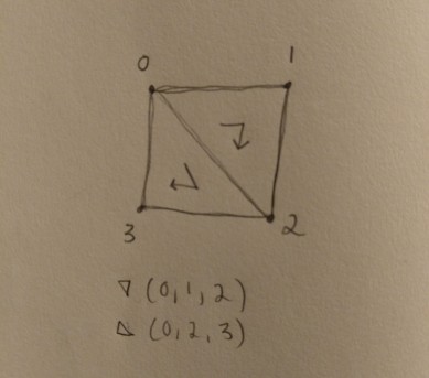
To understand how these offsets work, let’s look at an example of the correct offsets for the top quad. You’re going to replace your CreateQuad() call with the following:
// top
shape.CreateQuad(new Vector3(-2, 0, 0), // widthDir
                 new Vector3(0, 0, 2),  // lengthDir
                 new Vector3(0, 0, 0)); // pos
Our box is 2 units wide, which is why we use 2 for the direction here. Since our top quad lies flat on the X/Z plane, our width and length direction use only X and Z, and Y is 0. Our offset is 0 so that we can use this position as reference for the rest.
As an example of how position works, let’s look at our bottom quad. Since our box side length is 2, our bottom quad is going to be translate -2 on the y axis. Since its direction is going opposite of the top quad on the X-axis, it also needs to be translated -2 on the X-axis.
// bottom
shape.CreateQuad(newVector3(2, 0, 0),    // widthDir
                 newVector3(0, 0, 2),    // lengthDir
                 newVector3(-2, -2, 0)); // pos
Try filling out the remaining 4 quads without any help without looking at the final solution!
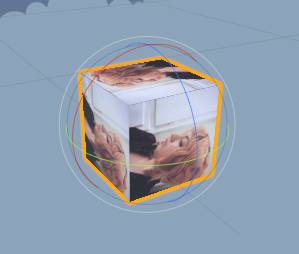
Congrats, you finished! You should now have a complete cube- something like the following:
Fin
If you get stuck, or just need to see the answer in action, feel free to view and download final code for a procedural cube here. Don’t forget to check the file titled Shape in the same folder! It’s under a non-commercial open source license. ^^
You should be ready now to delve into algorithms for more complicated shapes. You don’t have to 100% understand everything at this point; you just need a basic idea of how the geometry and normals for this cube came together. I find that a more advanced understand of topics comes with practice, not study.
In addition, the rest of the geometry tutorials skip normal and UV calculation since:
- Normal calculation is the same algorithm for any triangle.
- UVs are hard for complicated shapes! Ain’t nobody got time for that!
Part 3 will explain an algorithm for texturing any kind of crazy procedural geometry called tri-planar texturing, which avoids all of our UV woes!
If y’all have any questions about writing procedural geometry or shaders in Unity, I’m happy to share as much as I know. I’m not an expert, but I’m always willing to help other indie devs 🙂 And do give me feedback about the tutorials, I love hearing from y’all!
Good luck,
Lin Reid @so_good_lin

Wonderfuk tutorial. I always loved procedural generation but everytime I would watch a tutorial about it, I felt that I was just hard-copying and not really understanding what I was doing. I feel much more confident and I will def. try out to make more complex shapes, thank you.
LikeLike